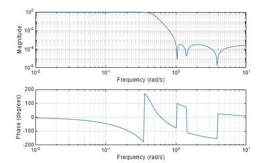

The ADC on the TIVA LaunchPad has only 12 bits of resolution distributed between 0 and 3.3 V, which means any unwanted signal due to aliasing needs to be attenuated enough to fit within the 0.8 mV quantization step size of the ADC – in other words, unwanted signal with an amplitude of less than 0.4 mV at the ADC input will, for the most part, not be included in the digital representation of the signal. So for a 4th order Chebyshev filter with 1 dB passband ripple, 12 kHz cutoff, and 22 kHz stop frequency, the highest achievable stopband attenuation is 30 dB.ģ0 dB corresponds to a linear gain of at most 0.032 V/V at 22 kHz (a gain that only decreases as the frequency increases beyond 22 kHz).

In our case, we want the filter order to be no larger than n = 4, so instead we’ll calculate the largest stopband attenuation that can be achieved given the rest of the filter parameters. Based on the equations 3.27 and 3.28 given in chapter 3 of Ludeman’s textbook, one can calculate the required filter order to realize a given set of Chebyshev filter specifications. So, by choosing a 1 dB passband ripple, the attenuation at the cut-off frequency will be 1 dB as well.Īs for the filter order, let’s select a 4th order filter mainly out of convenience: since many op-amp ICs are two op-amps in one, we can realize two 2nd-order filter stages using one IC.Īt this point, all the response parameters are defined except for the stopband attenuation (1/A^2). As per the ideal Chebyshev response curve above, the passband ripple is the same as the attenuation at the cut-off frequency.

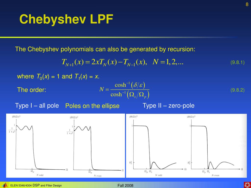
In this application, let’s set a maximum 10% reduction in the signal magnitude in the passband this corresponds to 1 dB of allowable passband ripple. The Chebyshev response allows us to have a sharper transition from pass to stop band if we’re willing to accept more passband ripple. Now let’s select the maximum passband ripple. So, I selected 12 kHz for the cut-off frequency this means the 1 rad/s cut-off frequency shown in the above Chebyshev response curve will be scaled to 12000 * 2π rad/s (as per the low-pass to low-pass filter transformation described in Chapter 3 of Ludeman’s textbook cited above). Why 12 kHz instead of 10 or 14? This is where I’m making an educated guess in balancing the need to capture the desired frequency content against the need to not build an overly complicated filter circuit. Even though humans can hear sounds as high as 20 kHz (depending on the person), most commonly encountered sounds exist below 12 kHz as shown by this frequency plot of various common sounds. So this should be set as low as reasonably possible. The lower the cut-off frequency, the less sharp the transition between the cut-off and stop bands, the lower the filter order, and the simpler the circuit. Next, the cut-off frequency (at which the linear gain is equal to 1/(1+ϵ^2)) needs to be selected. This curve is shown for a normalized even-order (n) low pass filter whose cut-off frequency is 1 rad/s.įirst, I’m going to select the stop frequency to be the Nyquist frequency of the standard CD audio sampling rate of 44.1 kHz, so let Ω r = 22000 * 2π rad/s. The design procedure starts by putting numbers to the ideal Chebyshev response curve, quoted from page 137 below (included here under fair dealing copyright guidelines): Ludeman’s “Fundamentals of Digital Signal Processing” (1986, Harper & Row Publishers Inc.), specifically in Chapter 3, “Analog Filter Design”. Instead, I found a middle ground by following a paper-and-pencil design procedure presented in Lonnie C. For this project I wanted to work through the design process employed by these programs, but I also didn’t want to spend time deriving the filter response nor re-inventing circuit topologies.

#Chebyshev analog filter designer app software
There are many online calculators and “canned” software packages that give the electronic component values based on a user-supplied filter response. In this post, let’s put some numbers to the response so that we can realize the filter as an electronic circuit. In my last filter design post, I selected a Chebyshev filter response as the best fit for the bispectrum visualizer.


 0 kommentar(er)
